Fenestration Anchorage
Installation considerations to ensure safe and reliable framing systems

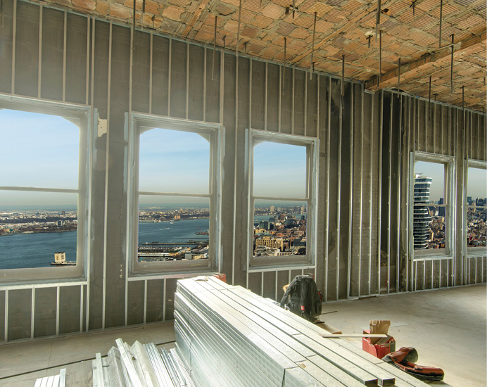
Above: The physical anchorage of an aluminum window is critical to ensure that it performs and operates as designed and tested. Photo credit: Oleg March and Travis Mark.
Commercial fenestration systems, which typically feature broad expanses of glass and lengthy sections of framing, tend to be subjected to significant static and dynamic forces on joints and anchors imposed by dead weight, winds, differential thermal expansion, seismic movement and even bomb detonations. Accommodating such forces includes the selection and use of proper fasteners to safely and reliably transfer loads to the building framework at designated anchor locations.
Improper anchorage could pose a threat to the safety of the structure’s occupants, notably injury from flying shards of broken glass. Being key elements in the load path, all fasteners should be analyzed to ensure that the material strength, thickness and quantity are adequate.
Specification guidelines
Specifying the type, class and performance grade of a fenestration product to meet the North American Fenestration Standard, or NAFS, indicates that the product meets a specific design pressure as tested in one specific anchorage system. In the field, however, fenestration products are often installed with various mullions, transoms, subframe systems or substrates that could require vastly different anchorage systems, or fastener location and spacing, than those tested in the laboratory. These anchorage and fastener differences create several variables that may affect the overall design pressure performance of the installed product.
Fortunately, no matter which anchor system is utilized, the principal engineering methodology does not change and substantive guidance on the analytical process is available. For example, the companion documents AAMA 2501, Voluntary Guideline for Engineering Analysis of Anchorage Systems for Fenestration Products, and AAMA TIR-A14, Fenestration Anchorage Guidelines, both FGIA publications, comprise an appropriate reference to verify that any anchorage system – including those that differ from what was used for testing in the laboratory – conforms to the project specifications.
AAMA 2501 outlines the minimum requirements for structural analysis by engineering calculation that can be referenced in project specifications and contract documents. Note that the analysis of curtain wall systems is more complex and is therefore not covered.
For the fasteners, the mode of failure could be any (but are not limited to) of the following: the material being fastened through or to (bearing or pull-out and/or pull-over), or the fastener material itself (shear, tension or combined loading). There are different rules and guidelines associated with fastener use in different building substrates—metal, wood and masonry—that govern the type, size and placement of anchors.
The basic procedure for conducting the engineering analysis of the anchorage system is listed, along with the recommended content of the engineering analysis report.
As described in the companion document, AAMA TIR-A14, the mode of failure for the material and fasteners along the load path of each anchor can change. Each component in the load path should be analyzed to assure that the material, material thickness and quantity of screws and/or fasteners is adequate for the load.
3-step analysis process
AAMA TIR-A14 describes a three-step process for anchorage design.
Step 1: Check the material being anchored
For the material, the mode of failure could be loading along the weak axis of the framing member, bending or buckling. Specifically, if shear is present, then the bearing strength of the base needs to be checked. If tension is present, then pull-over needs to be considered. Analysis equations for both factors, as well as for pull-over of flat head fasteners, are provided for reference.
Step 2: Check the fastener
For the fasteners, the mode of failure could be the same as that of the material being anchored (bearing or pull out/pull-over) or of the anchor material itself (shear, tension or combined loading). Aside from using AAMA TIR-A9 for load values of “generic” fasteners, many manufacturers publish their own load table specific to their fasteners, which gives allowable loads to which the calculated loads can be compared. The total tensile or shear load, divided by the allowable strength, must be 1.0 or less. Where anchors are loaded simultaneously in tension and shear, the sum of the load/strength quotients for tension and for shear, when added together, must be 1.0 or less.
Step 3: Check the material to which is being fastened
For the base material, bearing or pull-out and/or pull-over govern. The shear and/or tension in the fastener is compared to the allowable bearing (shear) and fastener pull-out of the base material. For fastener pull-out in aluminum substrates, reference is made to the Aluminum Association’s Aluminum Design Manual.
AAMA TIR-A14 also looks at the anchoring implications for four different building envelope substrates: metal, wood, concrete and concrete masonry units (CMU) or red face brick.
Analysis and accommodation of the various forces on anchorage systems can help ensure glass expanses will continue to deliver their intended function with minimal danger of becoming dislodged or breaking.


